Lucky's Series 3

Restoring, modifying, fettling or just enjoying your RX7 ? Share it with us here...
Lucky
VIP User
VIP User
Posts: 2685
Joined: Mon Nov 07, 2011 8:30 pm
Location: Worthing, UK
Been thanked: 5 times

Re: Lucky's Series 3

Post by Lucky »

Right, so back in the real world...

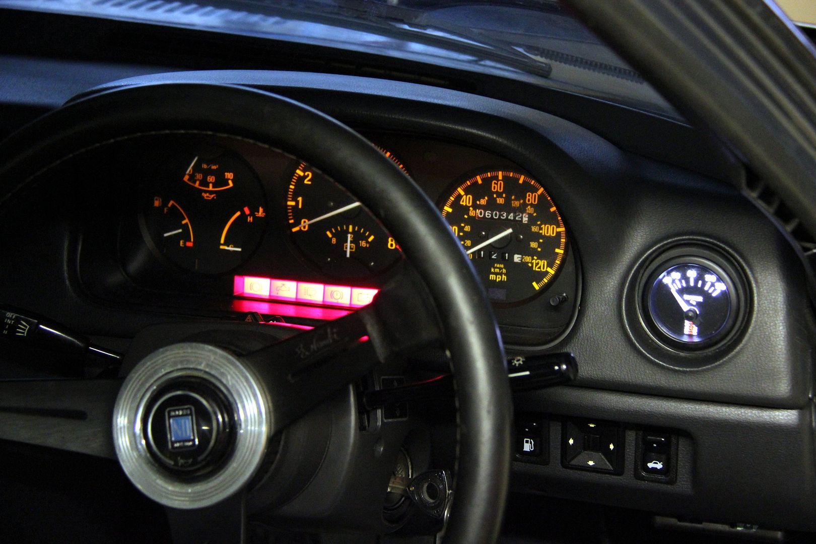
At first I thought this may be annoying but I don't even notice it now. I mean the fact the water gauge is a lot brighter and a different colour to the rest of the dials. I was thinking about spraying some lacquer tinted with colour over it (or there's always the old school technique of a Quality Street wrapper) but to be honest I'll probably leave it well enough alone. Nice to have it working for a while before I screw it up
Image

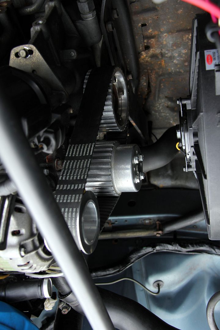
This is what the engine bay now looks like (now I've finally taken some pics in daylight!). The Gilmer set-up;
Image

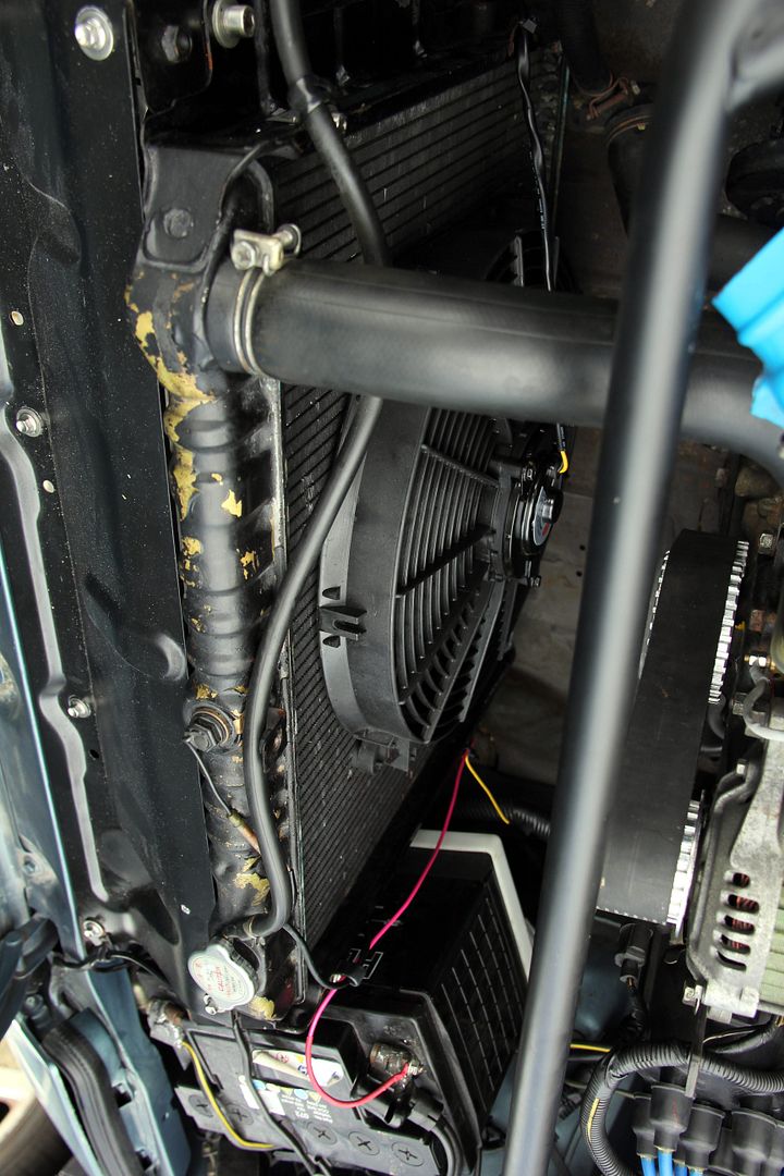
The fan; with hindsight, I probably could have got a 16" rather than 14" one but this seems plenty man enough to bring the temps down quickly enough. I can always upgrade it if need be if it struggles come summer
Image

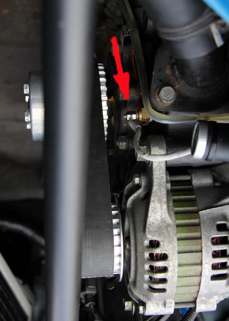
This is the sensor for the water temp gauge (arrowed). Much neater and less cumbersome than putting a hose insert in
Image

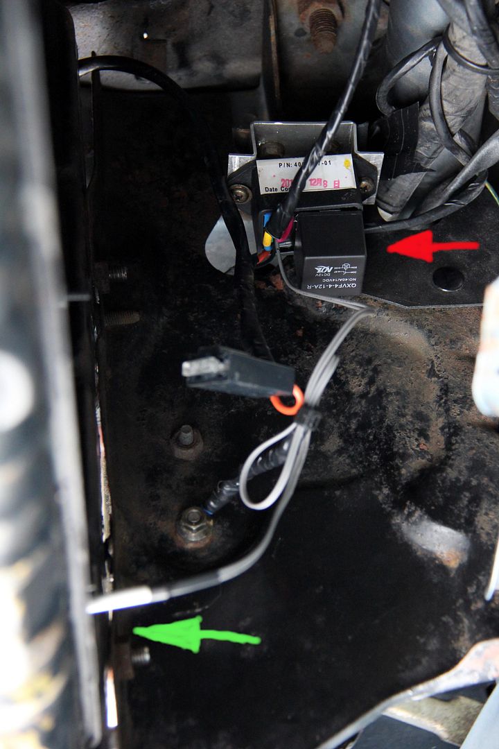
And this is all the wiring gubbins for the fan, mounted on a little bendy ally bracket in front of the rad (so it hopefully won't get cooked). The green arrow is the actual sensor; as I said before you just insert it between the tubes of the radiator core so there's no need to cut hoses, stick probes in under jubilee clips, etc. The red arrow is the module itself; relay on top, fuse currently dangling by its wiring (solution to follow when errr, when I can think of one)
Image

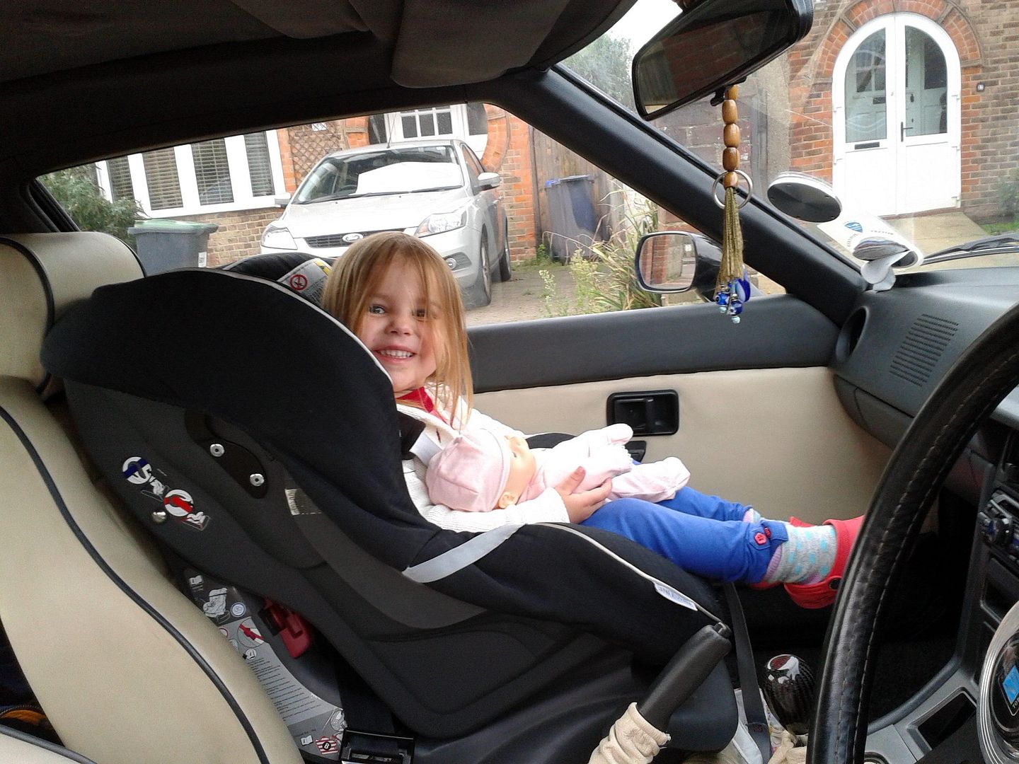
Trouble is, now I have to take out and paint the side panels for the radiator and the engine undertray, now I've realised how gnarly they are. So anyway, took it out of for a good long drive and let it get nice and hot. No repeat of the previous control box fry-up so definitely seems like that was a defective one. Temperature was getting a bit high before the fan cut in, so re-adjusted the controller and now it cuts in round about 90 degrees, goes off five degrees below that. Hurrah! The car now gets the Niah-cat seal of approval;
Image

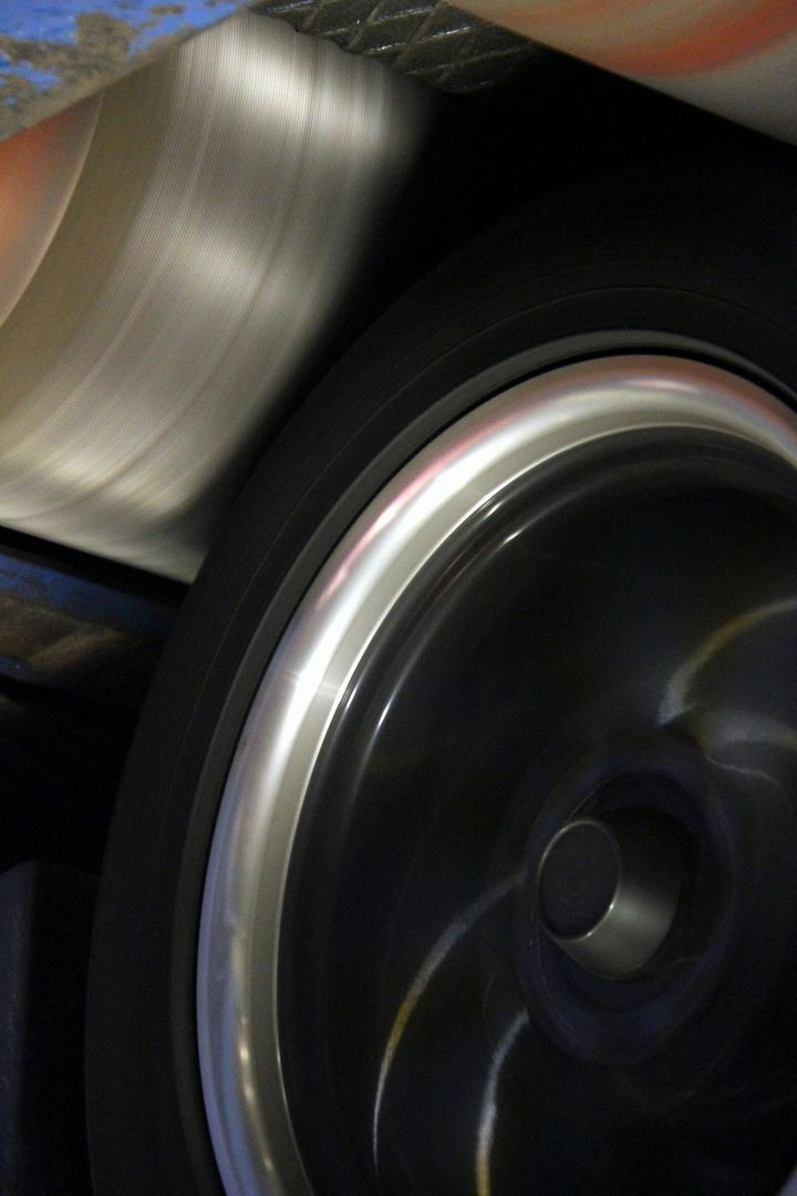
and to celebrate we strapped it down and did a bit of this
Image

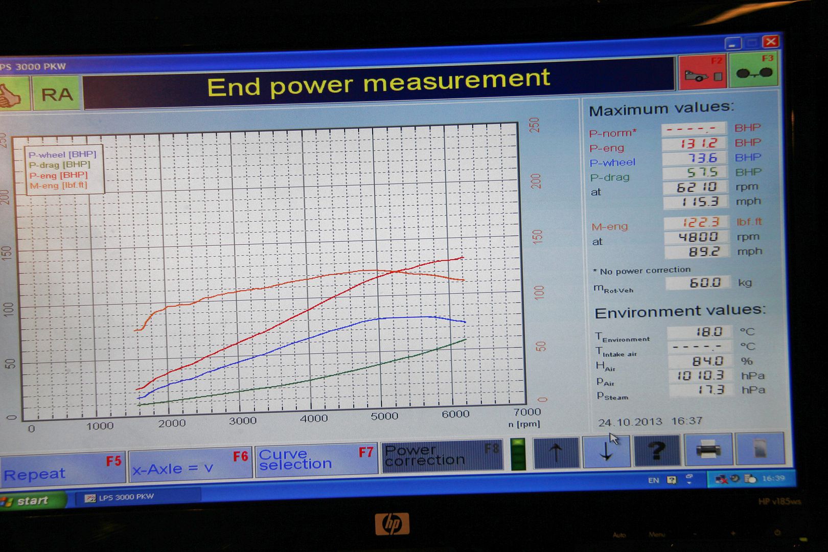
partly out of scientific curiosity, partly because we need a baseline to see what improvements come from the new built engine. If and when it ever happens! Anyway, this is what it made with no adjustments at all;
Image

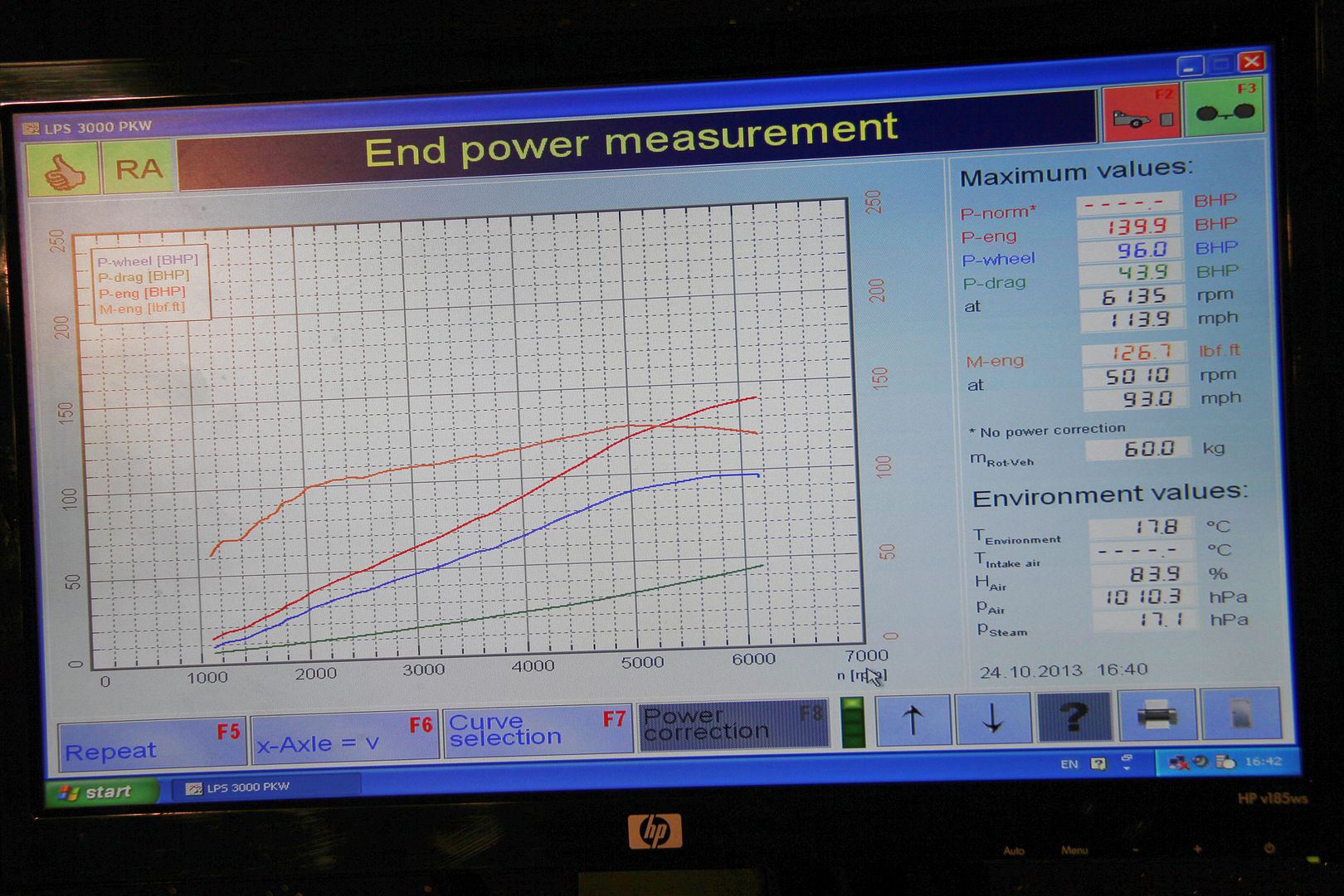
131 horsepower is more than Mazda quoted when it was new, so that was quite pleasing. After a bit of ignition and fueling tweakery it we ran it up again. Here's a video of my car on the dyno and not blowing up, which makes a nice change after the FD

http://www.youtube.com/watch?v=viEOQfy_ ... I42xzwg5mw

Image
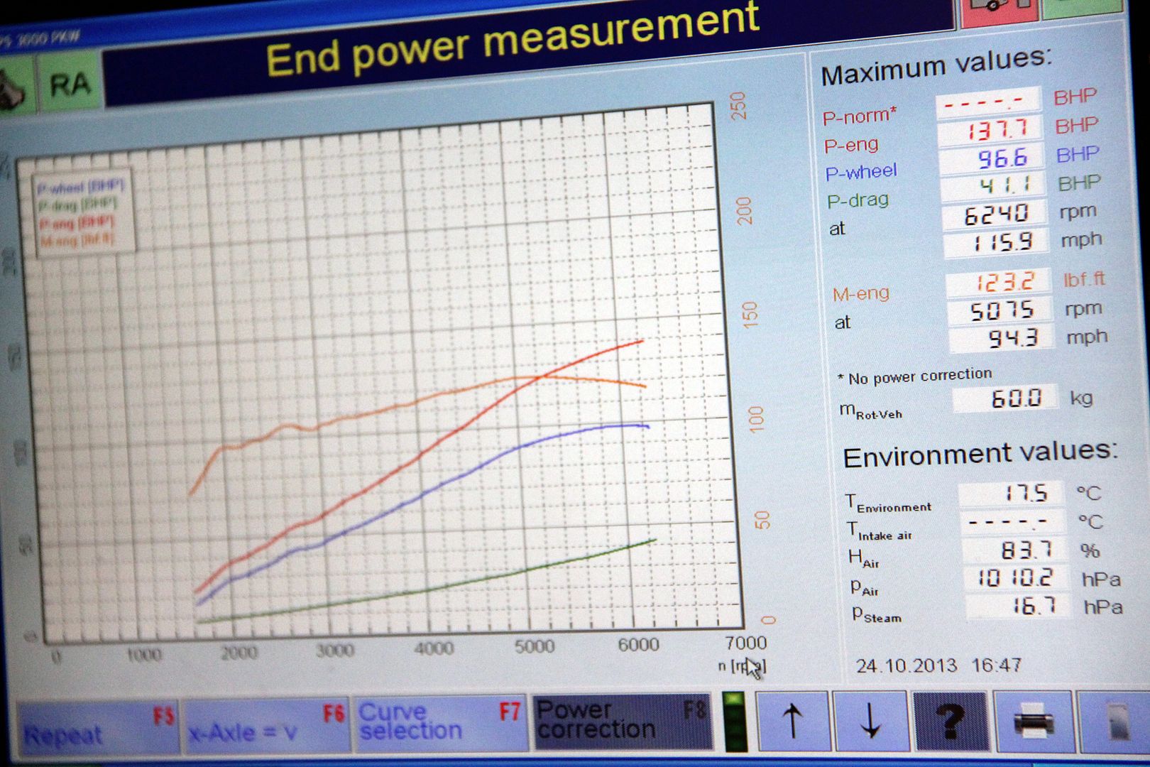
and after that run we made 139.9 horsepowerz! Mind you, the car didn't want to idle and pickup with that level of tune, so we backed things off a bit and tried again with a slight compromise setting


http://www.youtube.com/watch?v=xLxjqf2A ... I42xzwg5mw

Image

So, ended the day on 137.7 flywheel horsepower. Which I'm happy with. Even though it's nearly three hundred less than the FD it doesn't feel especially slow and tedious. It's still not enough, though. Next step; porting! :twisted:
User avatar
ian65
Admin
Admin
Posts: 6402
Joined: Wed Mar 30, 2011 12:11 am
Has thanked: 315 times
Been thanked: 376 times

Re: Lucky's Series 3

Post by ian65 »

on a car that's 28 yrs old, that's quite impressive to see it's putting out that much more than the stock figures..... just goes to show how power sapping that original exhaust and emission control stuff is.

1999 Jaguar XJR V8 Supercharged

1992 Peugeot 205 1.9 GTI
2003 Mercedes SLK 200 Kompressor
TOOL
VIP User
VIP User
Posts: 2598
Joined: Thu Sep 01, 2011 10:30 am
Location: Switzerland
Been thanked: 24 times

Re: Lucky's Series 3

Post by TOOL »

Wow, a dyno printout.

More than Carl ever managed. Mind you, he made just shy of a million horsepower at the fly with a headwind and the windows down by licking his finger and sticking it in the air.

You should be happy with that for a stocker with headers.
Back in the UK for the summer, maybe longer......
Lucky
VIP User
VIP User
Posts: 2685
Joined: Mon Nov 07, 2011 8:30 pm
Location: Worthing, UK
Been thanked: 5 times

Re: Lucky's Series 3

Post by Lucky »

Yeah, pleased with that :D I'd have been happy to even equal stock after nearly three decades, but to put and extra 20bhp or so on top was definitely a result. As for posting dyno graphs, in my experience the only reason for NOT posting them is if you've something to hide ;)
KiwiDave
VIP User
VIP User
Posts: 2268
Joined: Sat Nov 05, 2011 8:07 pm
Location: Feltham, Southwest London
Has thanked: 482 times
Been thanked: 192 times

Re: Lucky's Series 3

Post by KiwiDave »

Lucky wrote: with hindsight, I probably could have got a 16" rather than 14" one but this seems plenty man enough. I can always upgrade it if need be if it struggles
Good to see a man happy with his equipment ;)
1985 Sunrise Red S3 TWR
2006 Mercedes CLK 280 Sport AMG
Lucky
VIP User
VIP User
Posts: 2685
Joined: Mon Nov 07, 2011 8:30 pm
Location: Worthing, UK
Been thanked: 5 times

Re: Lucky's Series 3

Post by Lucky »

Some weirdness discovered today. But first, some more of the mind-numbingly trivial mods that give me so much fun and everyone else an excuse to roll their eyes heavenwards :lol: Firstly, an essential finishing touch... and haven't I told you before that it's all about the details?

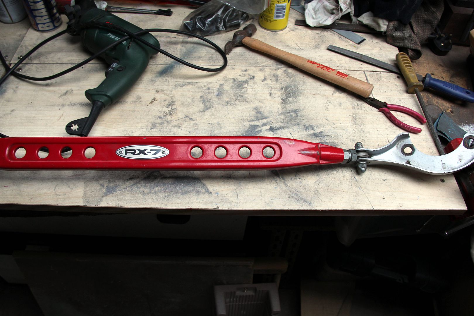
Step one; take one FD stock strut brace. Drill out the rivets;
Image

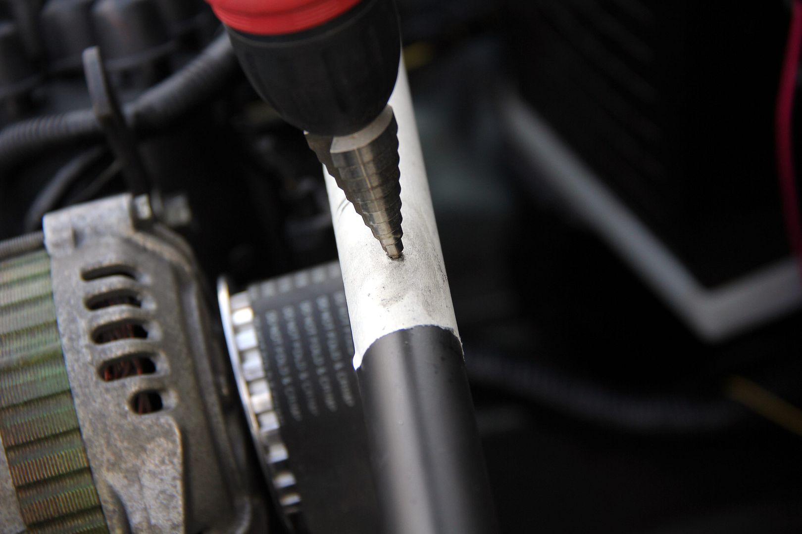
step two; do some measuring. Tradition would have it you do this twice and cut once. Or in this case, drill once. What ever did we do before step-bits? Changed drill bits a lot of times, I suppose :roll:
Image

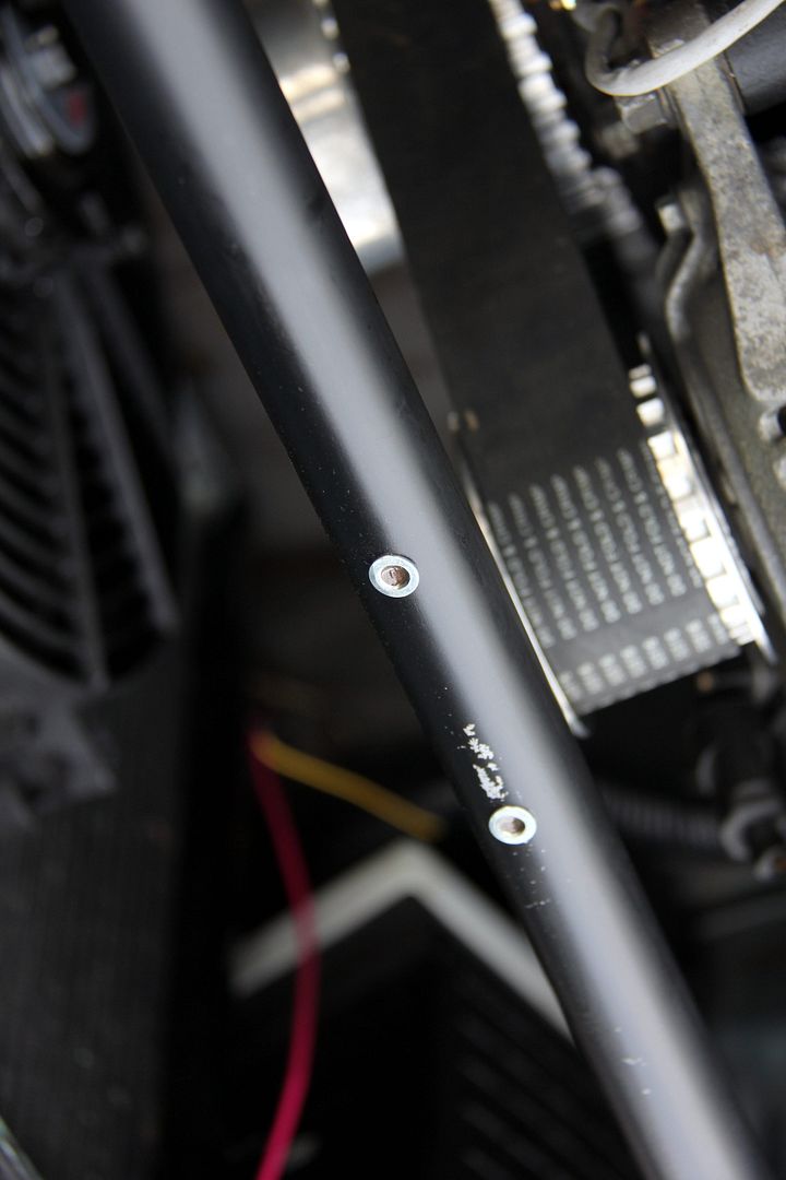
step three; get all Herculesian with the rivnuts. Thought about just using rivets like the original but in all likelihood I may well re-paint the brace, or maybe powder coat it. Just as well, since even the masking tape pulled some paint off, doesn't bode well for the longevity of the current finish. Rivnuts mean it's a lot easier to remove the plaque if I do re-paint
Image

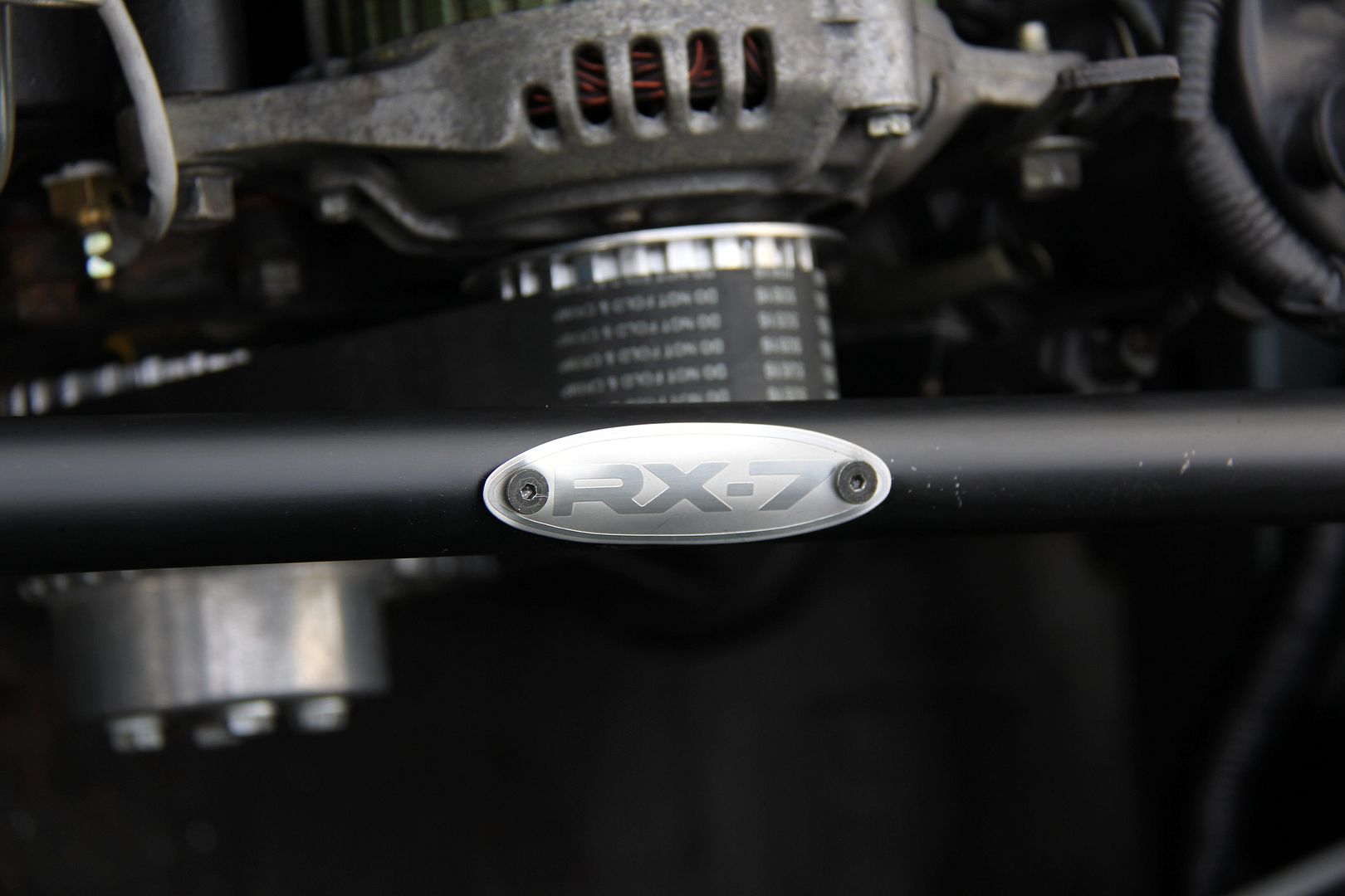
Step four; attach plaque and bask in how awesome you are. Even though I know damned well I've a small pot with some button head M4 stainless bolts in it somewhere in the garage, I'm damned if I can find them. So they'll turn up after the ones I just ordered on eBay show up, then. These are a temporary measure
Image


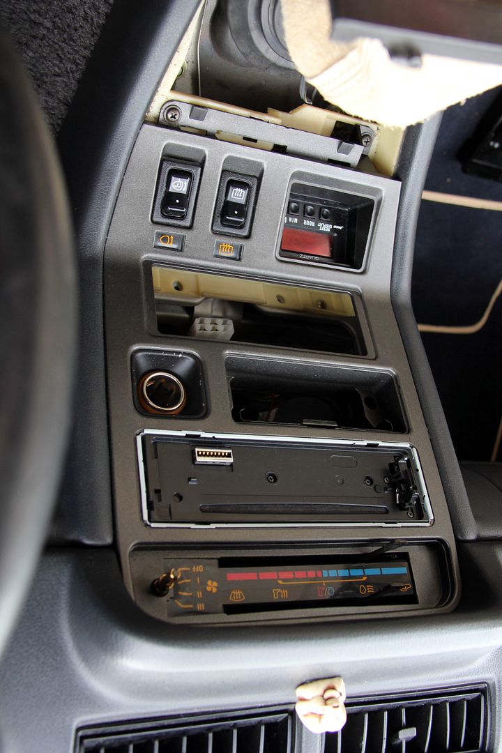
Second job completed today involved the removal of the centre console. Which was suprisingly easy; pull off the heater knobs, unclip the stereo fascia surround; two screws beneath the gearstick surround panel, two behind the ashtray and two under the top lip and it all pulls out. The main snag was that I couldn't see any way of disconnecting the cigarette lighter or removing the entire unit, so I could only pull the fascia out as far as the wires allowed.

Image

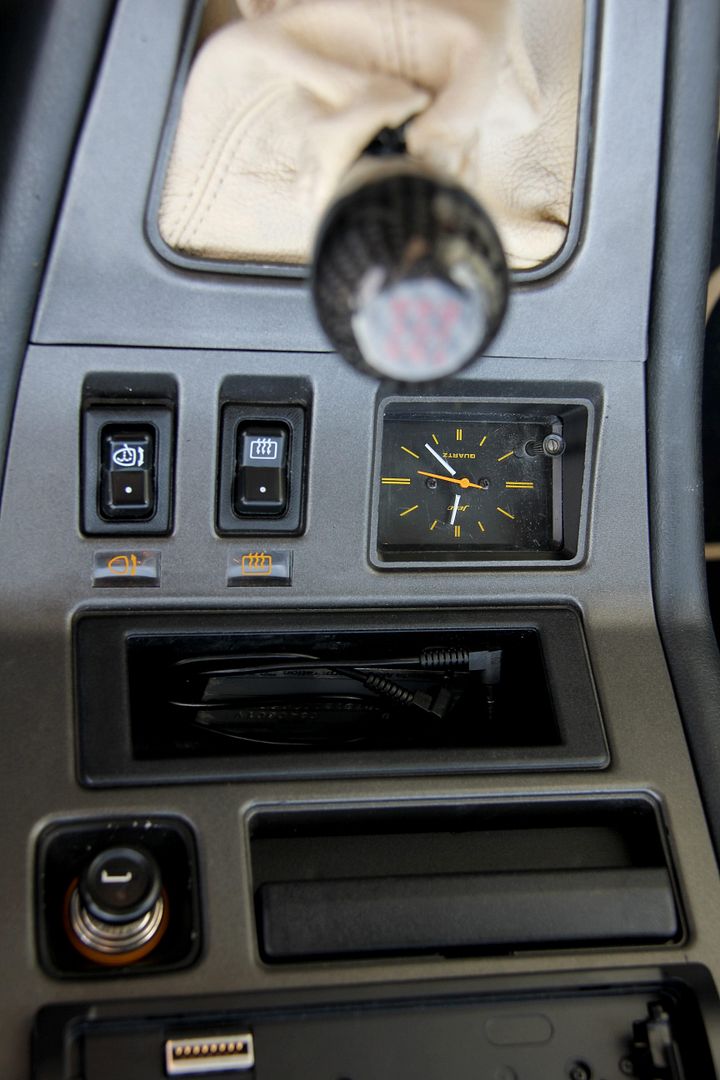
This was all good as besides the reason I wanted to get in there, I also discovered the reason the headlight valet switch didn't work; it had fallen apart and al the bits were in the gearstick plate! A bit of puzzling managed to clip it all back together successfully, so that's a bonus. The pupose of all this was to swap the horrid digital 80s clock for a nice original analogue one with proper hands, courtesy of Mark K. The wiring is slightly different, but the plug is the same. I think (though I may be wrong) that the digital clock might have another wire that tells it to dim when the lights are on or something. Dunno. Anyway, it all seems to work so I don't really care!

Image

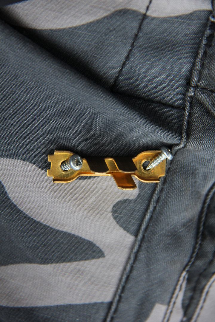
And it looks a thousand times more awesome, which is the entire point. Now to the weirdness. The cubby box thing pulls out from a couple of clips (the tray below the ashtray and above the clock, yeah). When I did this I discovered that there's a big nylon electrical plug connected to the back, though the back of the tray itself is blind. Further investigation showed the terminals on the back of the box can be unscrewed;

Image

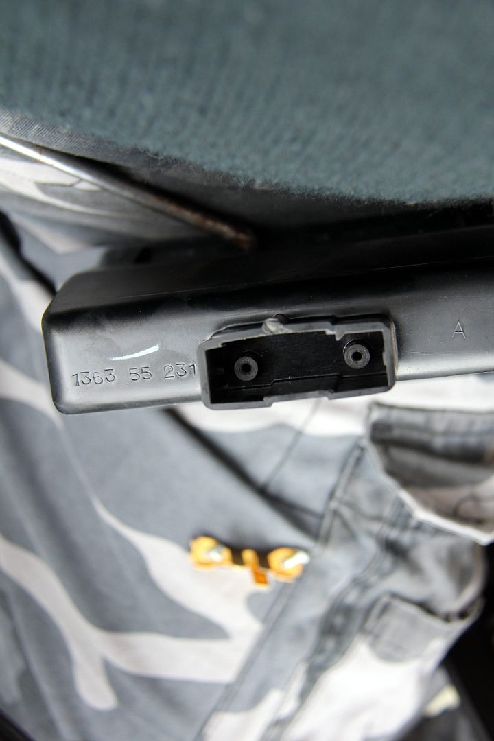
but behind them is nothing, just a blank on the back of the tray;

Image

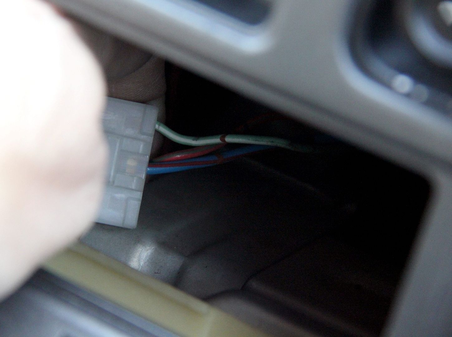
would this have been a light on some models or something? Seems a lot of effort to go to for no reason I can fathom out. The plug as three wires going into the back of it thus, though I didn't really have time to dismantle the whole dash to see where they went;
Image

Completely baffling. Welcoming opinions :?
Chud
VIP User
VIP User
Posts: 933
Joined: Fri Apr 01, 2011 7:35 am
Location: North Dorset, UK
Has thanked: 3 times
Been thanked: 111 times

Re: Lucky's Series 3

Post by Chud »

Maybe JDM spec ones came with a graphic equaliser that fitted in the cubby hole slot and thats the power/lighting plug for it?
instagram: tymboooo

1980 series 1 RX7 x2
1983 series 2 RX7
1975 RX3 Coupe
1956 VW split screen kombi
1966 Porsche 912
User avatar
ian65
Admin
Admin
Posts: 6402
Joined: Wed Mar 30, 2011 12:11 am
Has thanked: 315 times
Been thanked: 376 times

Re: Lucky's Series 3

Post by ian65 »

Keith's got an enlightening theory on this connector plug

1999 Jaguar XJR V8 Supercharged

1992 Peugeot 205 1.9 GTI
2003 Mercedes SLK 200 Kompressor
Lucky
VIP User
VIP User
Posts: 2685
Joined: Mon Nov 07, 2011 8:30 pm
Location: Worthing, UK
Been thanked: 5 times

Re: Lucky's Series 3

Post by Lucky »

ian65 wrote:Keith's got an enlightening theory on this connector plug
and it is.....? :?
User avatar
ian65
Admin
Admin
Posts: 6402
Joined: Wed Mar 30, 2011 12:11 am
Has thanked: 315 times
Been thanked: 376 times

Re: Lucky's Series 3

Post by ian65 »

Lucky wrote:
ian65 wrote:Keith's got an enlightening theory on this connector plug
and it is.....? :?
enlightening!


no doubt he'll explain it when he logs on.

1999 Jaguar XJR V8 Supercharged

1992 Peugeot 205 1.9 GTI
2003 Mercedes SLK 200 Kompressor
Post Reply

Return to “RX7 Rides and projects”