Relay Check Lamp (8598)
Posted: Tue May 24, 2022 9:18 pm
Something I've not looked at before, but tucked under the dash, near the "CPU" box on the driver's side is this item (case removed to show innards):
What does it do? Well it illuminates the brake fault light on the dash if one or both of the brake lights aren't working.
There was one of these relays attached to one of two CPU units that gt_james passed to me at Goodwood last Saturday for testing.
By a weird coincidence, Dave Collins, another FB owner who attended on Saturday, mentioned that his "Relay Check Lamp" had gone faulty and he'd bridged it out to stop an intermittently flashing warning light on his dash.
I decided today to check the wiring diagrams and trace the circuitry to see how this device works, using Jame's relay unit, with the aim of repairing Dave's faulty one later (which he will drop to me when I see him again in July).
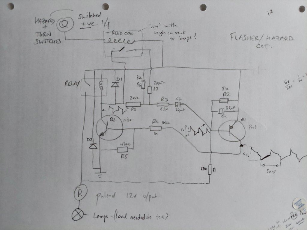
The circuit is very simple:
When the brakes are applied, the stop light switch (top right in diagram) applies positive 12 volts to the unit. If the correct current (about 4 amps) flows through the reed relay coil, then the reed switch closes. This effectively grounds the base of the D571 transistor, turning it off. With no current flowing through the transistor, the dash warning light will remain off.
If one, or both, brake lights has failed, then insufficient current flows through the reed coil to activate it. With the reed open, current flows from the +12volts supply through the 2 x 1k resistors to the base of the transistor and turns it on, so illuminating the dash warning light.
From Dave's description, it would seem the most likely fault is the transistor allowing current to flow when the brake switch is off. Equivalent transistors are readily available, should this prove correct. Watch this space....
- 20220524_175550.jpg (85.45 KiB) Viewed 80794 times
What does it do? Well it illuminates the brake fault light on the dash if one or both of the brake lights aren't working.
There was one of these relays attached to one of two CPU units that gt_james passed to me at Goodwood last Saturday for testing.
By a weird coincidence, Dave Collins, another FB owner who attended on Saturday, mentioned that his "Relay Check Lamp" had gone faulty and he'd bridged it out to stop an intermittently flashing warning light on his dash.
I decided today to check the wiring diagrams and trace the circuitry to see how this device works, using Jame's relay unit, with the aim of repairing Dave's faulty one later (which he will drop to me when I see him again in July).
The circuit is very simple:
- 20220524_182612.jpg (64.62 KiB) Viewed 80794 times
When the brakes are applied, the stop light switch (top right in diagram) applies positive 12 volts to the unit. If the correct current (about 4 amps) flows through the reed relay coil, then the reed switch closes. This effectively grounds the base of the D571 transistor, turning it off. With no current flowing through the transistor, the dash warning light will remain off.
If one, or both, brake lights has failed, then insufficient current flows through the reed coil to activate it. With the reed open, current flows from the +12volts supply through the 2 x 1k resistors to the base of the transistor and turns it on, so illuminating the dash warning light.
From Dave's description, it would seem the most likely fault is the transistor allowing current to flow when the brake switch is off. Equivalent transistors are readily available, should this prove correct. Watch this space....