Soooo, I haz done another thing.
And this week it's been mostly making me wish I could weld. And that I had a pillar drill. But there you go, I can't and I haven't so I've just been making the best of what I've got. To be fair, I was taught rudimentary welding at agricultural college anyway so it was mostly about gluing gates back together or patching holes in tractor trailer sides. Probably the sort of welding best not practiced on your pride and joy. But if anyone ever needs any holes blowing in anything, I'm yer man.
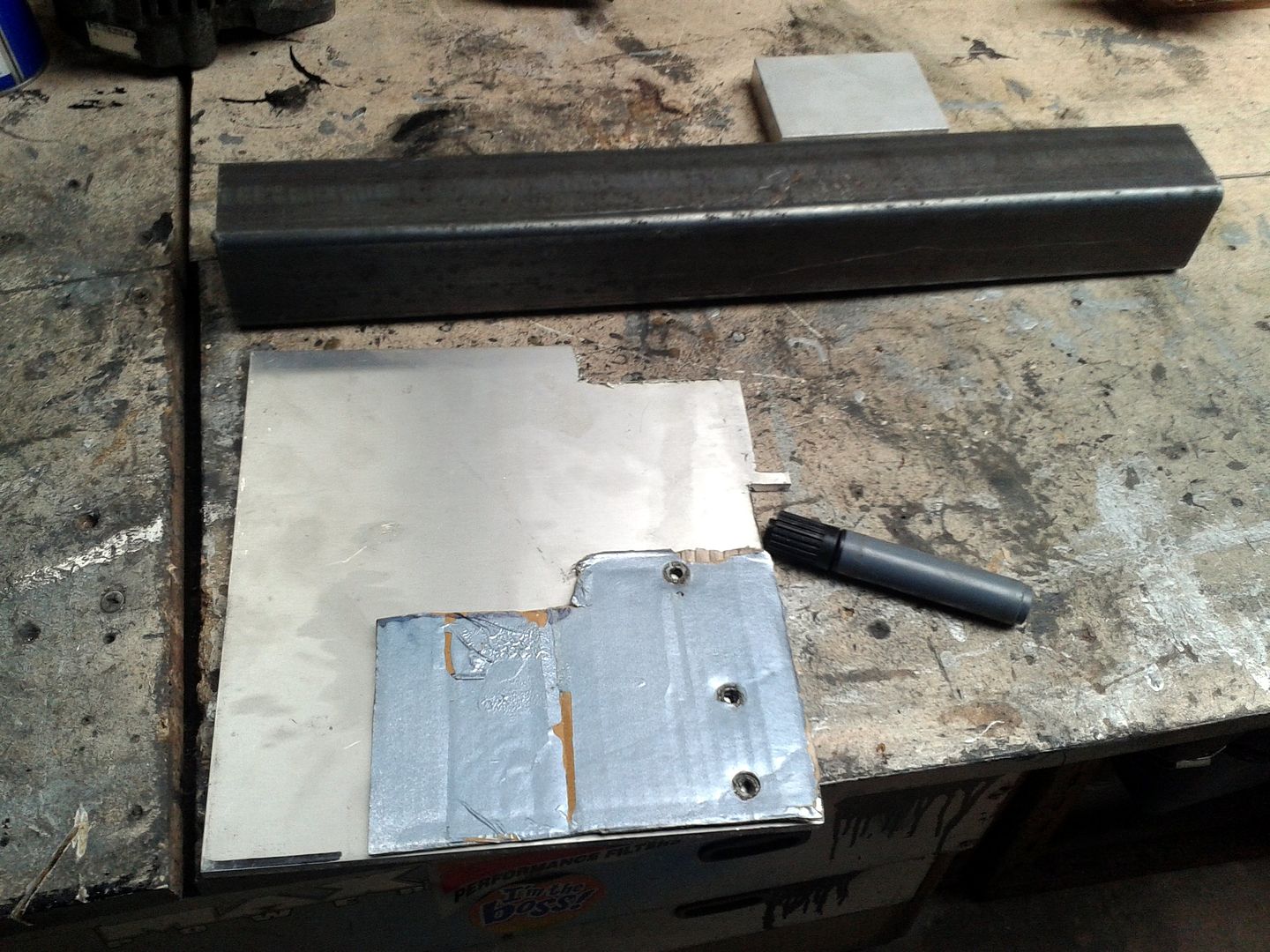
*ahem* anyway, this week's project begins, as all the best ones do, with a bit of cardboard that for the sake of argument we'll call a template.
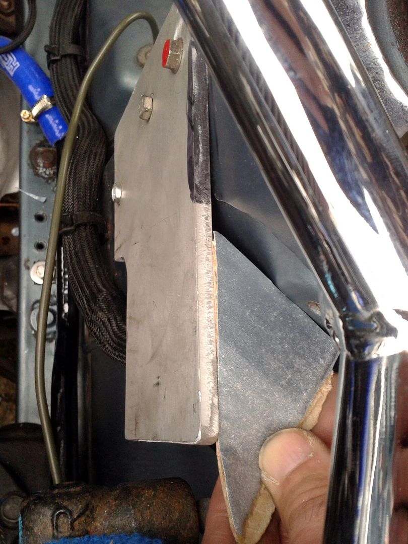
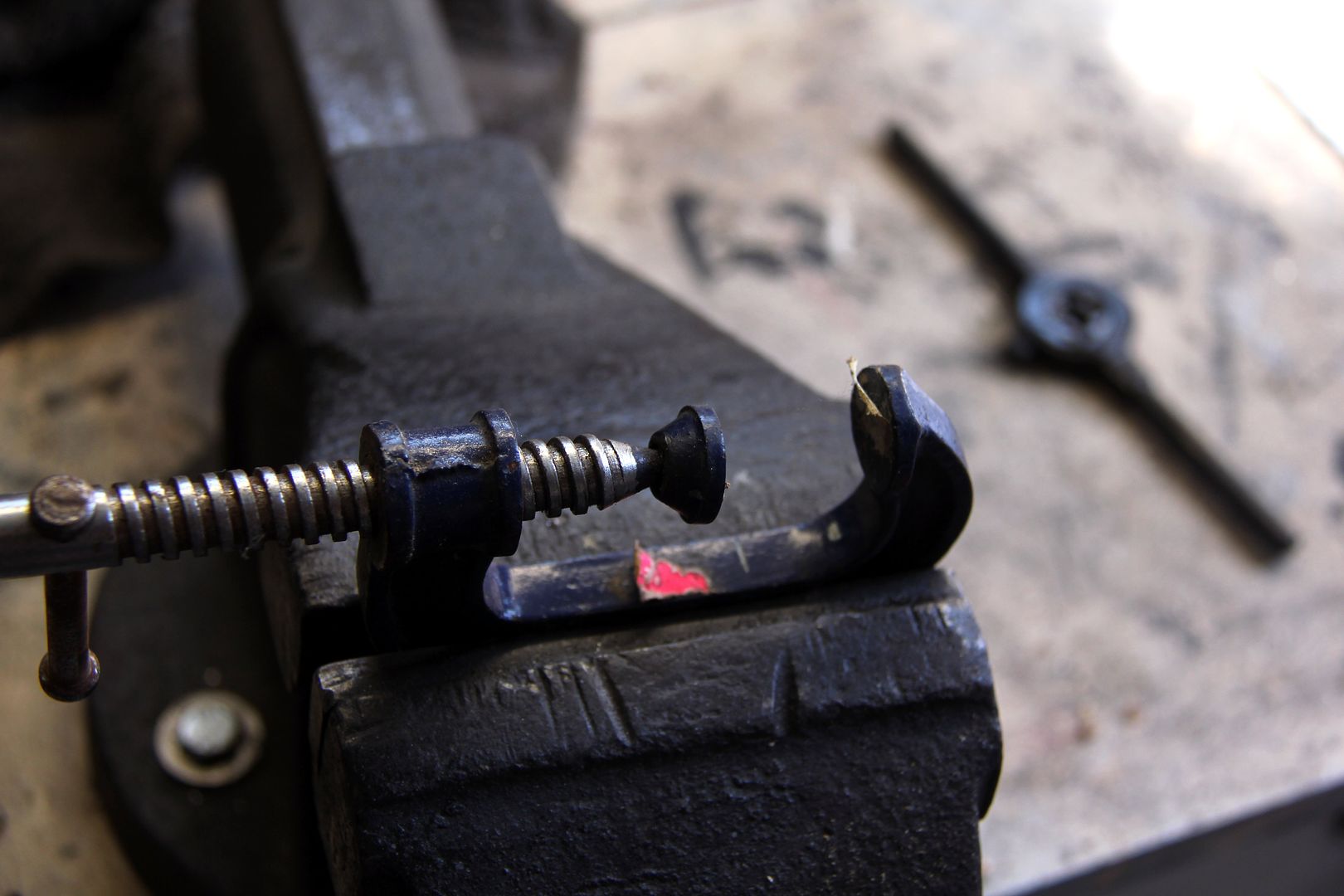
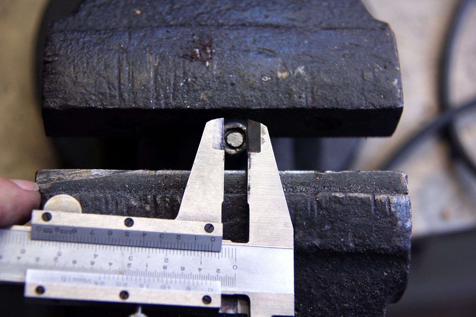
That bit of box-section will prove relevant later on, too. Once the main plate above was made up, I could bolt it into place and start work on a plate to brace it against the inside face of the strut tower as well. Here I'm using a special one-off tool I made specially for the purpose to establish the angle of deflection on the strut tower
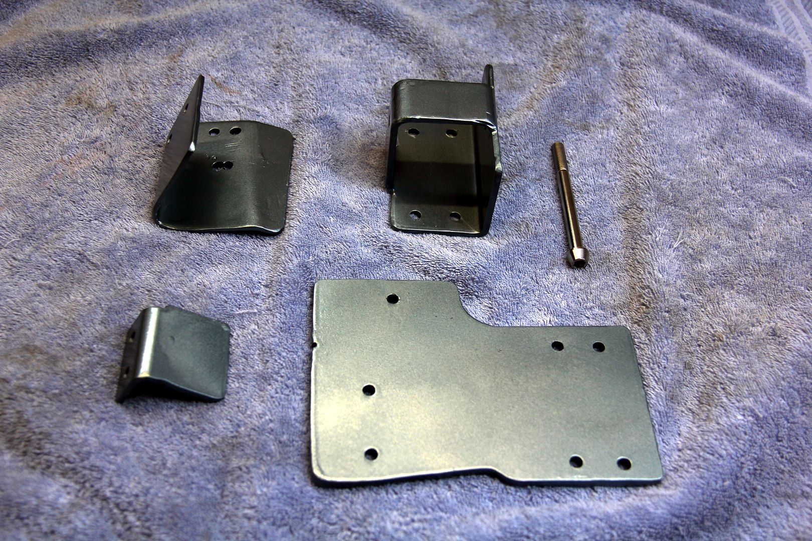
Yeah, OK, it's another bit of cardboard. Some of my best tools are made from cardboard. Anyway, I got 4mm wall box-section because it needs to be quite beefy otherwise there's no point in being there. Sadly, I didn't have any steel plate, so I had to make the main mount of of alloy. Albeit 6mm thick decent grade, so it's not going to bend either. But due the lack of weldability... and weld ability... it was going to need bolting together. Which meant a right pain in the posterior drilling the holes by hand
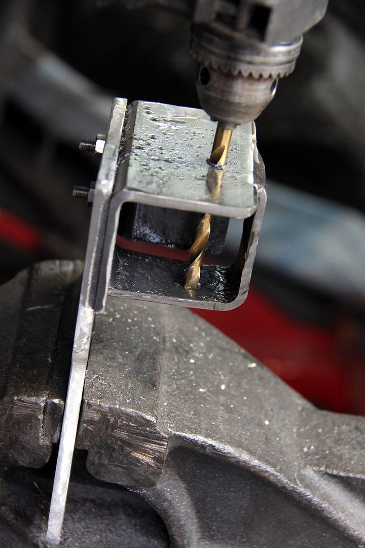
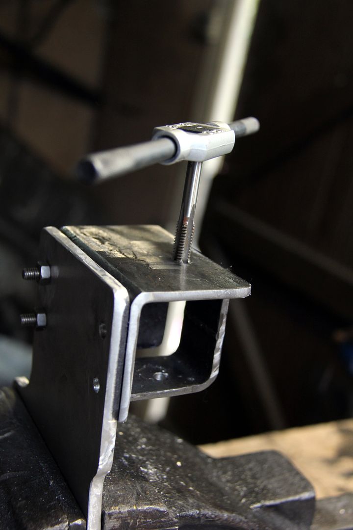
and then yet more fun tapping threads into the relevant holes by hand. Bummer. Still, at least it's a nice big M8x1.25 thread and so relatively easy to get straight.
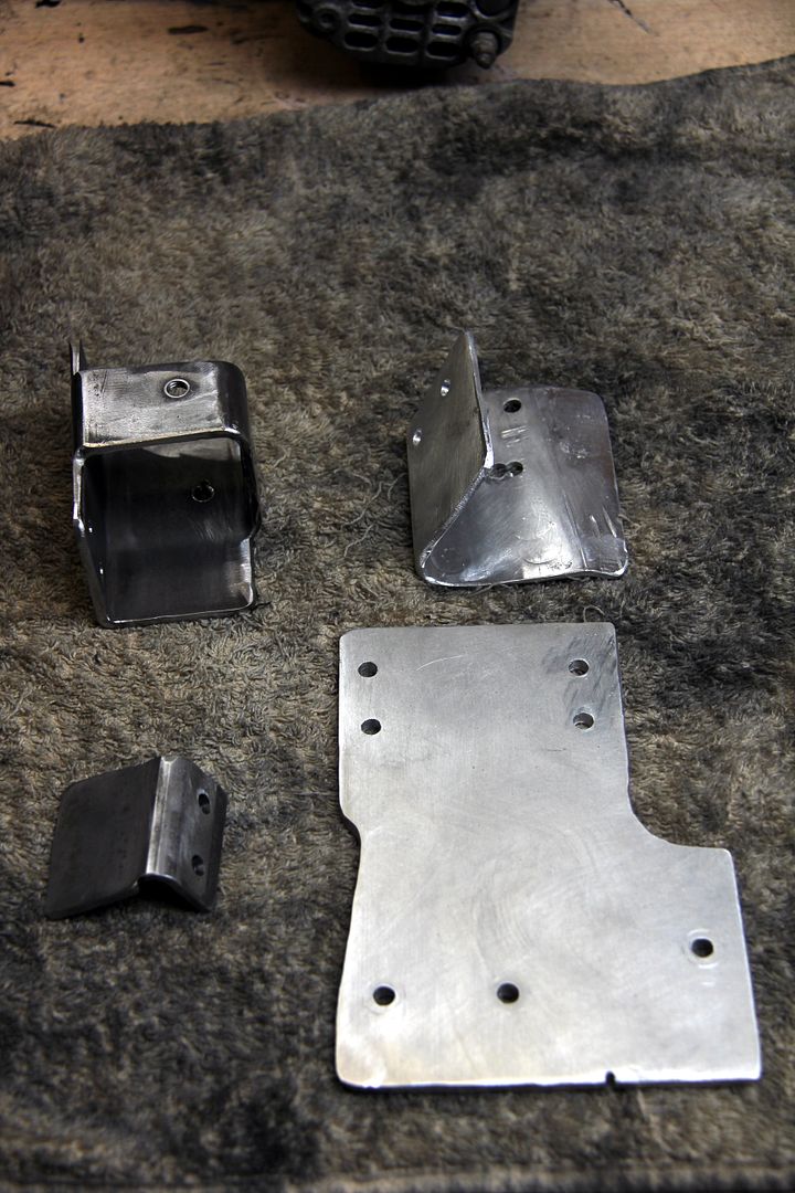
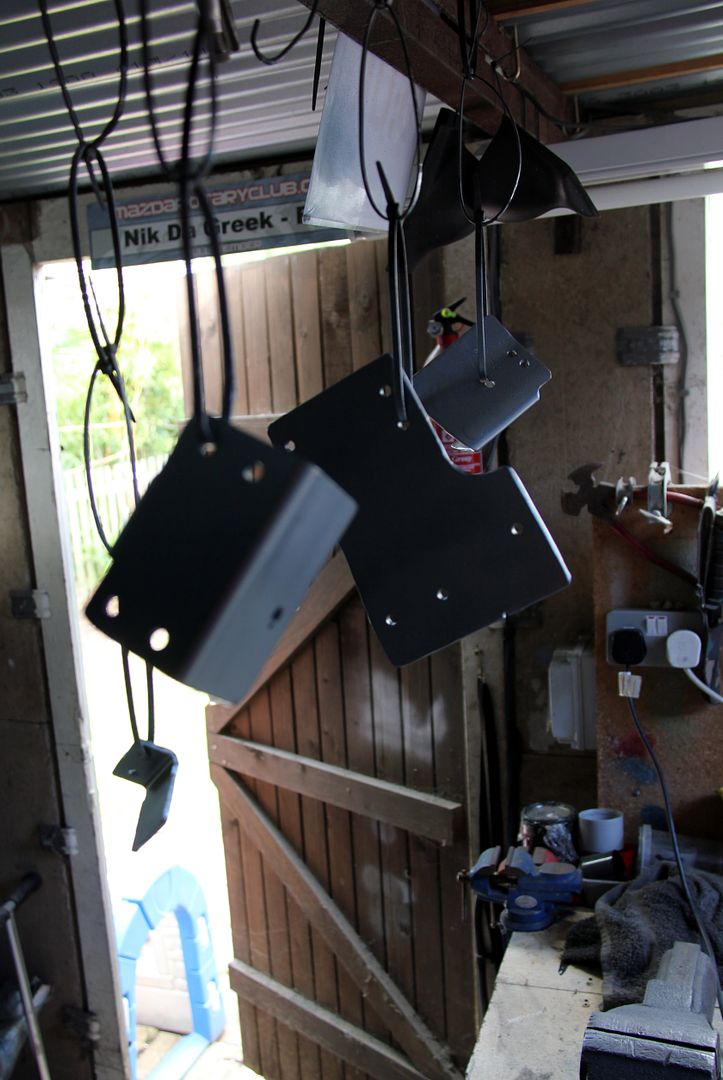
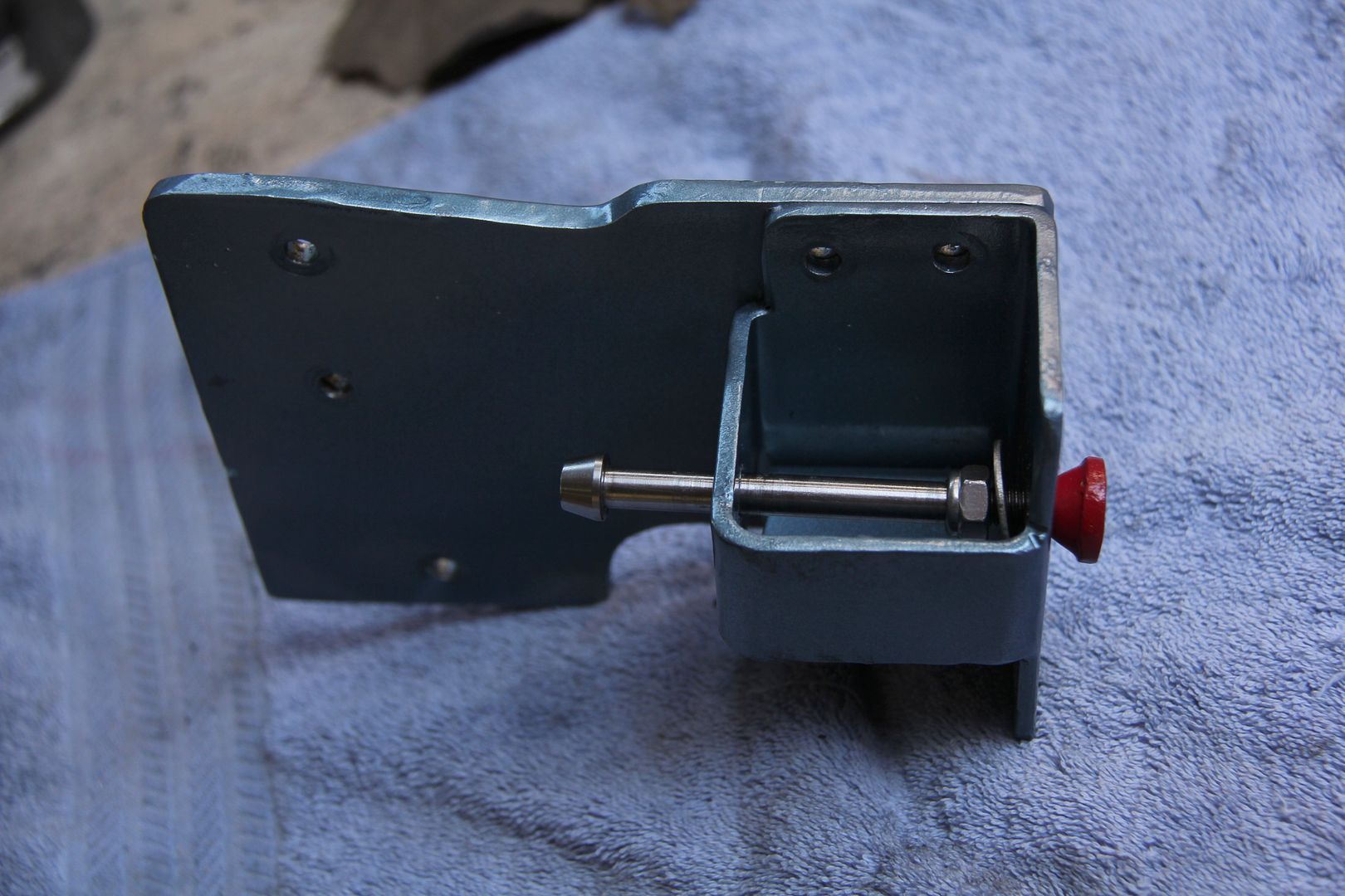
So eventually, I ended up with a nice kit of parts. The hardest part in fact was putting the bends into the triangulation piece as they were all at funny angles to each other, and due to the conical profile of the side of the strut tower, they weren't necessarily perpendicular to the main bracket. It was a proper PITA trying to get them right just with my bare hands, a vice, some heat and a big hammer. But it had to be done, this thing needed as much triangulation as possible. If it flexes then it may as well not be there.
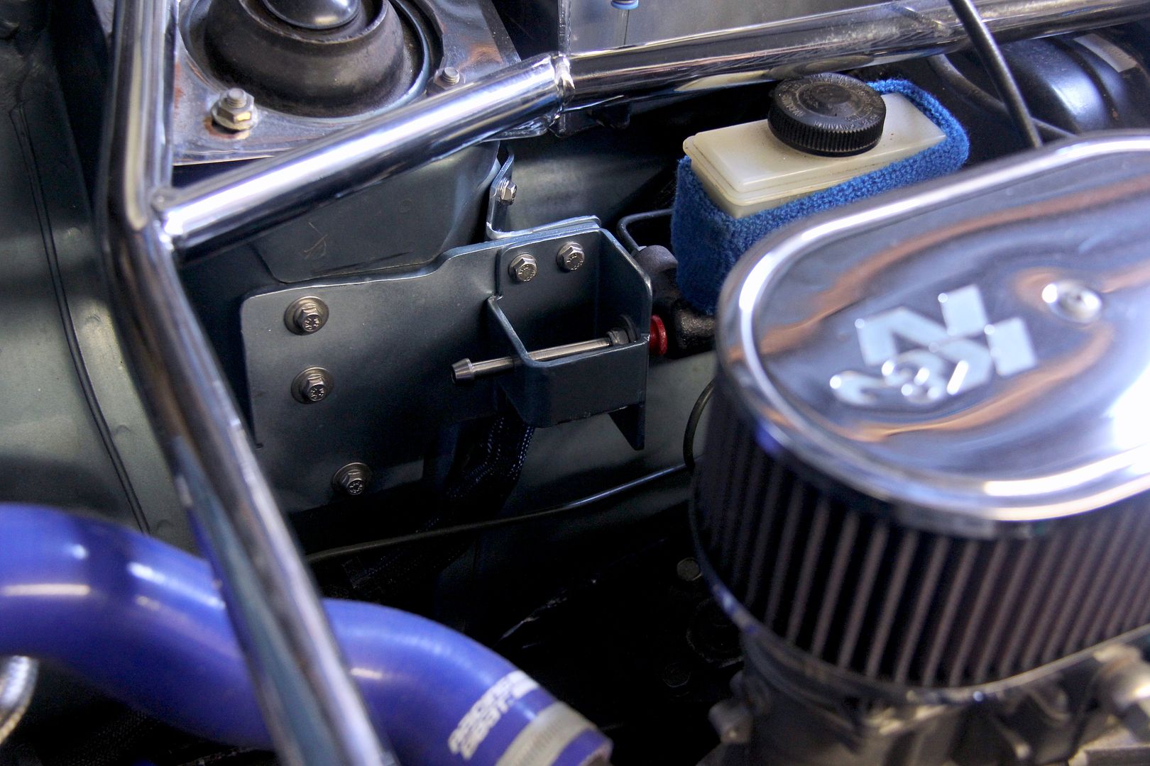
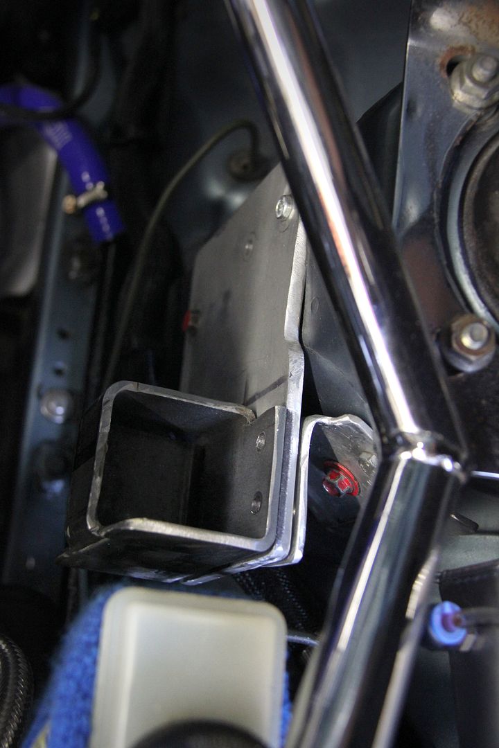
So it must be time for a test fit, then. Can you tell what it is yet?
If you answered "brake master cylinder stopper" then award yourself maximum cool points for cleverness. Yep, it's a brake master cylinder stopper, sho nuff. Now, I have to admit I was skeptical about these at first, figuring they were a nicely anodised Japanese gimmick for the car owner who has everything and wanted something else to colour-coordinate their other Super Now or Cusco jewelry with. Then I fitted one on the FD and the difference it made was amazing. Quite easily the simplest, most cost-effective way of improving the brake feel I've yet found. For anyone wondering, the idea is that the end of a threaded rod butts against the nose end of the master cylinder and thus prevents it from flexing the entire servo/firewall when the brake pedal is pressed. This slight movement is almost imperceptible unless you're looking for it, but it robs the pedal of feel and the first bit of every press on it is not working the brakes effectively as it's wasting force in bending the bulkhead.
Yeah, I know. I thought it was snake oil too, but I trust the evidence of my own eyes and nerves. The brakes on the FB are ...well, they're adequate. Certainly, they're adequate to the task of locking the wheels up if you stamp on them, but they just lack a bit of feel and always have, no matter what pads I use or how scrupulously I bleed them. I figured a brake stopper was the next thing to try. Trouble is, to the best of my knowledge, there isn't one available for the FB and no doubt it'd be for LHD anyway even if there was. So I couldn't just do what I did on the FD and buy in a nice Cusco one (anodised blue, if you were wondering). Hence this post, to which we shall now return...
While I was waiting for paint to dry... story of my life... I started looking around for a suitable end piece. I didn't just want the end of the bolt to butt against the master cylinder as it doesn't offer a big surface area and can be deflected off-centre. A poor innocent G-clamp looked like it could offer what I needed so I soon had it prepped for surgery
and brutally severed its extremity. Fortunately, it was the perfect internal diameter for my needs and so once I drilled out the remains of the balljoint I tapped a thread into it to suit the bolt. Don't worry, the G-clamp can still live a useful and productive life, just with a pointy bit rather than a flat bit on the end of its ermmm... whatever that prong is called on a G-clamp
Paint dry, it was time to get it done
Rather annoyingly, the bolt I'd ordered proved to be... well, a bolt. This was annoying because I'd wanted (and ordered) a set screw. Which AFAIK ought to be threaded along its entire length, not be mostly bloody shank like what I actually received. Turns out most all long titanium bolts are like this, presumably because manufacturers can't be bothered blunting their tooling rolling great big long threads into the hardest substance known to man. I tried my best to tap the rest of the bolt, but as this was premium grade titanium there was just no way. Not only was my tap not up to it (nor my feeble stick-like wrists) but it was impossible to find any way of holding the bolt secure enough that when the tap started to bite, it just turned the bolt in the vice jaws rather than cutting. So in the end I gave up. I wanted the bolt to thread into both sides of the box-brace but it wasn't going to happen so no point crying about it. To make myself happy again, I built it up to see how it looked
Good enough. To be fair, when it's all bolted in most of it is obscured down amongst other lumps of engine bay stuff anyway, but I figure if it's going to be there it may as well look as nice as it can. And here it is, in place. Looking as nice as it can
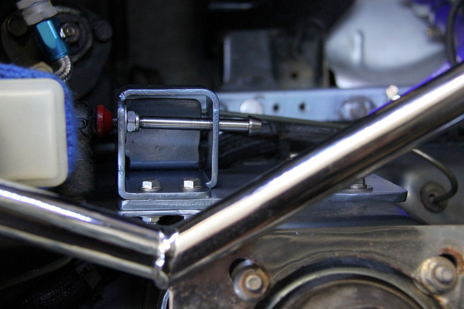
and now I have a nice firm brake pedal action and the world is a much better place than it was this time last week. Hurrah!