1983 Elford Turbo

Restoring, modifying, fettling or just enjoying your RX7 ? Share it with us here...
Moomin
Posts: 26
Joined: Fri Apr 15, 2022 8:07 pm
Has thanked: 10 times
Been thanked: 29 times

1983 Elford Turbo

Post by Moomin »

I bought this from a friend after selling a few projects, decided that a rotary with no history, no mot and flat tyres was a very good idea :lol:

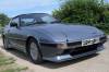
It's a 1983 (A Reg) Elford Turbo in Misty Blue, with no MOT history at all and a tax discs from 1992 it looks to have simply been sat unloved for the best part of 20 years. My friend enthusiastically fitted an Alu rad and oil cooler, took some interior trim off and then got bored.

Here it is after he dropped it off on a low loader...
PXL_20210819_173747234.MP.jpg
PXL_20210819_173747234.MP.jpg (338.78 KiB) Viewed 20947 times
PXL_20210819_173805614.MP.jpg
PXL_20210819_173805614.MP.jpg (335.72 KiB) Viewed 20947 times
It was then rolled into the garage where it has remained for 5 months gently being persuaded back into a useable condition. I hadn't expected (not having owned a retro Mazda) to find parts quiet so difficult to find at a reasonable price.

It has however now got; 4 new EBC discs and pads, rebuilt calipers all-round, new tie rods, new wheel bearings, new brake lines, all the bushes are polyflex. I've also done lots of other little jobs that escape my memory but its an enjoyable car to work on and I really look forward to putting it on it's wheels and finding it blows up in minutes of driving :lol: :lol:

I then looked for coilovers, £1000+ WTF! Make my own ones of those thanks...
PXL_20220420_172030905.jpg
PXL_20220420_172030905.jpg (157.14 KiB) Viewed 20947 times
I wasn't happy with the ball joints, so I stupidly attempted to replace them, resulting in a cracked wishbones. Again £200 each plus import! No thank you, make my own on the laser cutter...
wishbone.png
wishbone.png (215.98 KiB) Viewed 20947 times
I'd expected the car to be pretty rotten and was ready for a weldathon when I started stripping it... to my surprise and some cleaning later the inner wing looks like this!
PXL_20220420_171921537.jpg
PXL_20220420_171921537.jpg (171.83 KiB) Viewed 20947 times
The eagle eyed amongst you will have notice the awful ford 4 spokes the car arrived on, not only the wrong PCD but just totally the wrong look for the car. It now has a set of period correct Cheviot Sonics (those who know their wheels will know just how rare these are in the UK) sat on some hub adapters.
PXL_20220420_171928714.jpg
PXL_20220420_171928714.jpg (142.99 KiB) Viewed 20947 times
Now for the point I need your expertise... the turbo setup...
There is no evidence of any form of boost control, ECU or microcontroller anywhere, nor any evidence of one being fitted.
What it does / did have is...
PXL_20220420_172016909.jpg
PXL_20220420_172016909.jpg (155.75 KiB) Viewed 20947 times
Which I removed assuming it was some sort of emissions non-sense but having scrolled through other people posts now realise has a purpose?
I'm also confused as to how the vacuum advance should be setup in terms of where the tubes should or shouldn't go. They are currently paired and run to the carb via a single line!
PXL_20220420_171830885.jpg
PXL_20220420_171830885.jpg (194.14 KiB) Viewed 20947 times
PXL_20220420_171825464.jpg
PXL_20220420_171825464.jpg (208.26 KiB) Viewed 20947 times
My questions are:
What vacuum lines should go where?
What should the weird tube with the two ceramic discs be wired into?
Why is there a hard copper line (not shown) between the side of the turbo housing and the inlet manifold?

Many thanks sorry for the length of the ramblings!
KiwiDave
VIP User
VIP User
Posts: 2268
Joined: Sat Nov 05, 2011 8:07 pm
Location: Feltham, Southwest London
Has thanked: 482 times
Been thanked: 192 times

Re: 1983 Elford Turbo

Post by KiwiDave »

The vacuum advance setup is correct for your Elford. In original form, there was a plate that sat between the inlet manifold and the factory 4 barrel Nikki carb. This had connections for various vac lines including two from the distributor (1 from leading and 1 from trailing ignition).

Your SU inlet manifold has only one vacuum connection available. It works fine. I swapped out my 4 barrel for a twin SU setup and have the same 2 into 1 vac advance arrangement.
1985 Sunrise Red S3 TWR
2006 Mercedes CLK 280 Sport AMG
User avatar
ian65
Admin
Admin
Posts: 6402
Joined: Wed Mar 30, 2011 12:11 am
Has thanked: 315 times
Been thanked: 376 times

Re: 1983 Elford Turbo

Post by ian65 »

The vac advance is controlled differently on an Elford Turbo to a normally aspirated carb'd engine. There is a real danger of detonation as the turbo comes onto boost and the boost rises and in a rotary this can be catastrophic... it's very easy to blow a tip.
Elfords managed this by stopping the timing from advancing once the engine went onto boost and did so with a very simple but effective setup.
The 2 vac tubes from the dizzy join at a T-piece and then run as a single line to a blue dot solenoid... you can use the one from a standard 12a rats nest.

Another single vac line comes out of the back of the solenoid and runs to the little vac take off point on the carb mount.
So at this point the vac from the induction operates the vacuum advance as it would on a standard car. Elford wanted to retard the timing as the turbo went onto boost and basically although they didn't retard it as such, they did find a way to stop it from advancing.

The 2 pressure switches you have are mounted on the top of the engine over the flywheel inspection cover. The 0.1 pressure switch connects to the blue dot solenoid and the solenoid itself takes it's +12v supply from the back of the alternator.
The pressure switches sit on a little manifold which is itself connected to the main inlet manifold by a large vac line.

The result of all of this is when the engine is off boost the solenoid is open and the vac off the induction advances the timing as normal.
When the pressure switch detects boost however it goes to ground. This completes the 12v electrical circuit through the solenoid causing it to close and thereby shutting off the vac (automatic) advance in the dizzy.
When the engine comes back off boost the pressure switch stops grounding the solenoid, the solenoid re-opens and the automatic advance works normally again which gives good 'off-boost' drive-ability.

Image


There's probably some photos in my old threads on my Elford Turbo cars...

http://www.rx7fb.com/viewtopic.php?f=4&t=2174

http://www.rx7fb.com/viewtopic.php?f=21&t=1775


.

1999 Jaguar XJR V8 Supercharged

1992 Peugeot 205 1.9 GTI
2003 Mercedes SLK 200 Kompressor
User avatar
Hobbawobba
VIP User
VIP User
Posts: 1938
Joined: Tue Nov 01, 2011 9:44 pm
Location: Worcester - UK
Has thanked: 628 times
Been thanked: 218 times

Re: 1983 Elford Turbo

Post by Hobbawobba »

Nice intro there. Good score if you haven't found much rust aye! :clap: That control arm looks slick. Having access to a laser cutter must be really useful! :o
Moomin
Posts: 26
Joined: Fri Apr 15, 2022 8:07 pm
Has thanked: 10 times
Been thanked: 29 times

Re: 1983 Elford Turbo

Post by Moomin »

ian65 wrote: Tue Apr 26, 2022 10:51 pm The vac advance is controlled differently on an Elford Turbo to a normally aspirated carb'd engine. There is a real danger of detonation as the turbo comes onto boost and the boost rises and in a rotary this can be catastrophic... it's very easy to blow a tip.
Elfords managed this by stopping the timing from advancing once the engine went onto boost and did so with a very simple but effective setup.
The 2 vac tubes from the dizzy join at a T-piece and then run as a single line to a blue dot solenoid... you can use the one from a standard 12a rats nest.

Another single vac line comes out of the back of the solenoid and runs to the little vac take off point on the carb mount.
So at this point the vac from the induction operates the vacuum advance as it would on a standard car. Elford wanted to retard the timing as the turbo went onto boost and basically although they didn't retard it as such, they did find a way to stop it from advancing.

The 2 pressure switches you have are mounted on the top of the engine over the flywheel inspection cover. The 0.1 pressure switch connects to the blue dot solenoid and the solenoid itself takes it's +12v supply from the back of the alternator.
The pressure switches sit on a little manifold which is itself connected to the main inlet manifold by a large vac line.

The result of all of this is when the engine is off boost the solenoid is open and the vac off the induction advances the timing as normal.
When the pressure switch detects boost however it goes to ground. This completes the 12v electrical circuit through the solenoid causing it to close and thereby shutting off the vac (automatic) advance in the dizzy.
When the engine comes back off boost the pressure switch stops grounding the solenoid, the solenoid re-opens and the automatic advance works normally again which gives good 'off-boost' drive-ability.


There's probably some photos in my old threads on my Elford Turbo cars...

http://www.rx7fb.com/viewtopic.php?f=4&t=2174

http://www.rx7fb.com/viewtopic.php?f=21&t=1775


.

This is exactly what I need to know h[b[ h[b[

Thnkas so much Ian that should prevent me blowing it to pieces on the first drive W(p W(p W(p
User avatar
kenwhiteside
Posts: 217
Joined: Sat May 26, 2012 7:03 pm
Location: Hove
Has thanked: 2 times
Been thanked: 21 times

Re: 1983 Elford Turbo

Post by kenwhiteside »

Hello,

Good looking car there. I am fairly sure that’s a Japanese spec 12aT engine that’s had the injected turbo setup removed and the elford setup fitted. It looks to have the 12aT dizzy that retards with boost, note the screws on the vac actuators and it’s got the additional degas line from the rear iron and the oil feed for the turbo from the front iron.

If you use the elford setup that actuates the solinoid to cut the vacuum advance you will not make use of the boost retard on the 12aT dizzy.
User avatar
gt_james
VIP User
VIP User
Posts: 1067
Joined: Sun Apr 06, 2014 4:10 pm
Location: Tewkesbury UK
Has thanked: 114 times
Been thanked: 211 times

Re: 1983 Elford Turbo

Post by gt_james »

Cool project, and I like the new wheels! out of interest what size and PCD are the revolutions? I may be interested in them
Brankoboavista
Posts: 3
Joined: Sun May 23, 2021 12:11 am

Re: 1983 Elford Turbo

Post by Brankoboavista »

kenwhiteside wrote: Thu Jun 09, 2022 9:14 pm Hello,

Good looking car there. I am fairly sure that’s a Japanese spec 12aT engine that’s had the injected turbo setup removed and the elford setup fitted. It looks to have the 12aT dizzy that retards with boost, note the screws on the vac actuators and it’s got the additional degas line from the rear iron and the oil feed for the turbo from the front iron.

If you use the elford setup that actuates the solinoid to cut the vacuum advance you will not make use of the boost retard on the 12aT dizzy.

The vac line on the su carb only have vacuum, so when he want’s to use the retard of the dizzy’s i think he need the put the vac/boost line between the turbo and the inlet.

But the oem Japanse spec 12at turbo is a blow trough setup, so it’s getting vac or boost on the same port on top of the throttle.
Elford is a draw trough setup, so between the turbo and inlet there is allways a lot of vacuum I gues.

I’m dealing with the problem that i’m thinking my 12 enigine is detonate with the elford setup.
Missing the pressure switch so made it with other components.
Running 8 psi (waste gate opens).
In the beginning I was thinking to place a 12at dizzy, but now i’m thinking to lock the dizzy. Someone have a suggestion?
User avatar
kenwhiteside
Posts: 217
Joined: Sat May 26, 2012 7:03 pm
Location: Hove
Has thanked: 2 times
Been thanked: 21 times

Re: 1983 Elford Turbo

Post by kenwhiteside »

The jap spec 12aT is injected. No nether blow through or suck through.

8psi is over the standard setting but I am led to believe people have run 14psi without issues on an elford setup. Check your timing, should be set to standard and no more than 10deg at full centrifugal advance (vac advanced is blocked off on boost by solinoid system). Check leadingbto trailing split. Checking afr also worthwhile. If you cannot do this just clean the carb and ensure tuned correctly (float height, needle, use the lift pin to check idle mixture)

Tim
Moomin
Posts: 26
Joined: Fri Apr 15, 2022 8:07 pm
Has thanked: 10 times
Been thanked: 29 times

Re: 1983 Elford Turbo

Post by Moomin »

It's been months since an update so here goes.

Interior is pretty buggered so I've ditched the door cards chucked some PVC foam board in there to tidy it up a bit
PXL_20230408_130620836.jpg
PXL_20230408_130620836.jpg (289.82 KiB) Viewed 20208 times
The exhaust has been my main battle ground, in the form of leaks so many leaks. Manifold to engine, leak. Turbo to down pipe, leak. Mid box to back box, leak. I deleted the mid-box entirely, re-using the flange and a bit of straight pipe. The manifold needed machining flat as it was so corroded and warped.
PXL_20230411_101012493.jpg
PXL_20230411_101012493.jpg (170.79 KiB) Viewed 20208 times
I then chased the exhaust leak to the waste gate casting, and again machined the whole thing flat. I must have taken the exhaust and manifold off 10 times chasing this leak!!! :crazy:

For ages and ages it was chucking fuel into the engine at a great rate, I changed the pump, no effect, figure carb was dead. Then realised I'd blocked the breather pipe 🤣 instant solution 👌

Today I decided it was time to attempt a drive on the road, so I fired it up and off I went. To my delight it drove surprisingly well, I was concerned my hand made suspension setup was going to be completely crap. It wasn't, so pointy 👌

Things left to do:
Bleed brakes again as they are a bit spongey
Work out why the wing indicators don't work, despite new bulbs and cleaning.
Find some lowering springs for the rear that actually lower the car 🤣
PXL_20230408_130249013.MP.jpg
PXL_20230408_130249013.MP.jpg (303.94 KiB) Viewed 20208 times
Post Reply

Return to “RX7 Rides and projects”