Page 1 of 1

Module 8248

Posted: Sat Jul 23, 2022 8:38 pm
by Casey
I've figured out what this module does :thumbup:

A little challenge, does anyone know where this is located and it's function? The electrical screwdriver is shown to give some idea of scale, the module is ~45 x 45 mm, with a 6 pin connector. Clue - there is NO RELAY in the box.

20220723_185234.jpg
20220723_185234.jpg (72.92 KiB) Viewed 14008 times

Re: Module 8248

Posted: Mon Jul 25, 2022 10:40 am
by gt_james
located by the flasher cpu?

Re: Module 8248

Posted: Mon Jul 25, 2022 12:47 pm
by Casey
Yep :thumbup:

Re: Module 8248

Posted: Mon Jul 25, 2022 4:27 pm
by DKWW2000
Operates the Fuel Pump?

Re: Module 8248

Posted: Mon Jul 25, 2022 8:17 pm
by Casey
Waaaaay off Pete ;)

I'll give it another couple of days and reveal what I've found :D

Re: Module 8248

Posted: Mon Jul 25, 2022 8:38 pm
by ian65
Coolant level sensor....... what do I win?!

Re: Module 8248

Posted: Mon Jul 25, 2022 11:47 pm
by Casey
And we have a winner :clap: - but no prize :D

I'll post up some pics later and explain a little bit about how I think it works. TBH, it seems an overly complicated module for a simple function, which is odd for a car manufacturer who must be trying to shave off costs wherever possible.

Re: Module 8248

Posted: Tue Jul 26, 2022 3:59 pm
by Casey
Here's some more gen on this module. If faulty, there should not be difficult to replace any faulty component, there's nothing exotic in there.

Here's the PCB inside:
Coolant level PCB, component side.jpg
Coolant level PCB, component side.jpg (125.94 KiB) Viewed 13941 times


and this is my tracing of the circuitry:
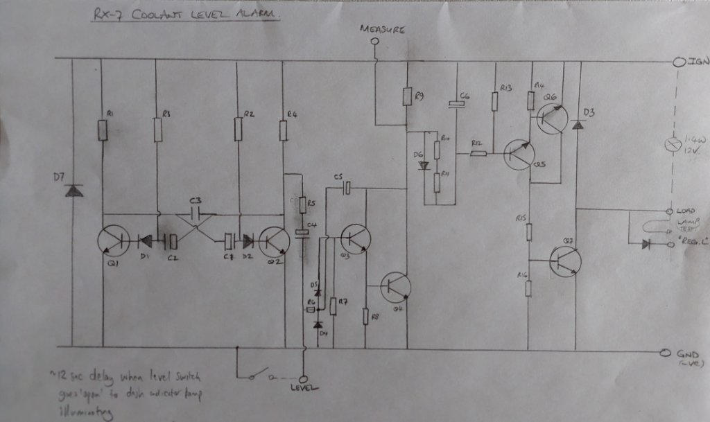
Coolant level circuitry.jpg
Coolant level circuitry.jpg (90.64 KiB) Viewed 13941 times

As far as I can work out, the basic operation of the circuit is as follows:

When the coolant level switch in the radiator is closed, the string of transistors; Q3, Q4, Q5, Q6 and Q7 are switched off, so no current flows through Q7 and the 1.4w lamp in the instrument cluster will be off.

When the coolant level drops, the switch goes open and Q1/Q2 provide a square wave voltage output (at collector of Q2, R4, R5) which slowly charges C4, switching on Q3/Q4, this slowly charges the large C6 capacitor (220 microfarads) and this then switches on Q5/Q6 and then Q7.

The charging of the capacitors delays the switching of Q7 for bout 12 seconds, so avoiding the coolant warning lamp from illuminating if the coolant is sloshing around, or forced to one side whilst cornering.

The diode, centre right of the diagram had me puzzled for a moment, then I realised that it is there to provide a lamp test function when the ignition is switched on, via the “Reg.L” connector.

I thought it worth recording this on here for posterity, as I couldn't find out much about this module on a quick internet search.

The "measure" pin on the connector (that's what is screen printed on the PCB) isn't connected, so it may provide a test point when the boards are checked by the manufacturer.

Re: Module 8248

Posted: Tue Jul 26, 2022 4:05 pm
by Casey
And here is the relevant wiring diagram, for reference:

Colant level sensor wiring marked.JPG
Colant level sensor wiring marked.JPG (139.88 KiB) Viewed 13940 times

Re: Module 8248

Posted: Tue Jul 26, 2022 7:04 pm
by ian65
bloody hell, that looks unnecessarily complicated.... great work Malcolm! Surely they could come up with something simpler and more cost effective than that.